
Low voltage short circuit impedance measurement is a basic item in routine test items. By comparing the short circuit impedance values measured before and after the transformer is impacted by the short circuit current, the degree of winding deformation can be preliminarily estimated based on the change in the short circuit impedance. The change in the low voltage short circuit impedance of the transformer after the short circuit current impact and the initial test should not be greater than 2%.
The low voltage short circuit impedance test is the most direct method to check whether the winding is deformed after the transformer is impacted by the short circuit current in operation or the transformer is impacted by mechanical force during transportation and installation. It is of great significance to determine whether the transformer can be put into operation, and it is also one of the bases for determining whether the transformer requires disassembly inspection.
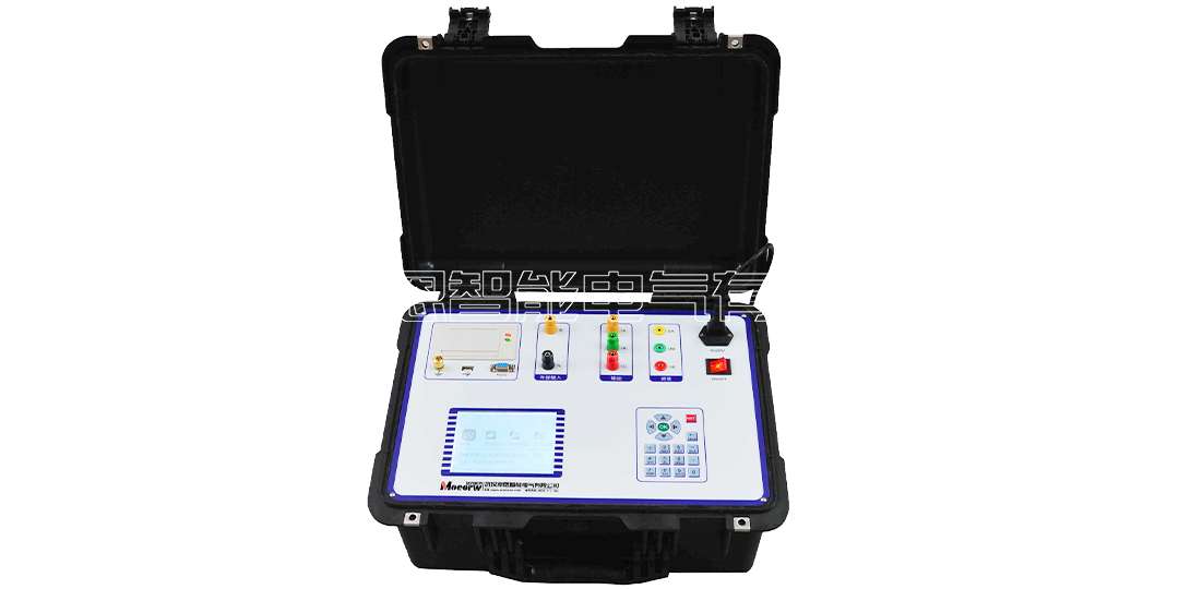
The MEBDR transformer short circuit impedance tester has an adjustable power supply output inside, which is particularly suitable for on-site low voltage short circuit impedance measurement of 110kV and above main transformers.
1. The instrument has an adjustable power output. Whether it is a single-phase or three-phase transformer, the instrument can complete the measurement of all winding pairs with only one wiring. The test and wiring are simple.
2. In addition to supporting internal power supply testing, it also supports external voltage regulator power supply testing.
3. It meets the test and algorithm specified in "DL/T1093-2008 Guidelines for Detection and Judgment of Reactance Method for Deformation of Power Transformer Windings".
4. "DL/T1093-2008" clearly stipulates: 5.4.1a, "In principle, single-phase parameters are tested by single-phase method"; 5.4.1e, "When the test results are abnormal, all winding pairs should be retested by single-phase method". The instrument adopts single-phase measurement method. For the three-phase transformer three-step voltage boost process, the short-circuit impedance, reactance and inductance of each phase can be automatically calculated.
5. The instrument adopts phase-locked loop technology inside, synchronously samples AC signals, and the measurement data is accurate.
6. The instrument can measure voltage, current, power, frequency, etc.
7. The single-machine measurement voltage and current range is wide, and it supports external CT and PT to further expand the measurement range.
8. Built-in non-power-off memory can store measurement data for a long time, and the instrument comes with a printer.
9. Support USB test data export for further analysis or storage, and support USB program update.
10. All English menus and operation prompts, simple and intuitive operation.
12. Transflective large-screen LCD, clear display under direct sunlight.
1. Measurement accuracy: voltage, current: 0.2 level
Power: COSφ>0.1: 0.5 level; COSφ≤0.1: 1.0 level
Impedance: COSφ>0.1: 0.5 level; COSφ≤0.1: 1.0 level
2. Voltage measurement range: AC 3V~600V
3. Internal power supply output range: voltage 0~250V, current 0~10A
4. Current measurement range: AC 0.2A~20A
5. Working temperature: -10℃~50℃
6. Working humidity: 0~80%
7. Working power supply: AC220V±10﹪ 50Hz±1Hz
8. Dimensions: 360mm×220mm×150mm
9. Instrument weight: 5kg
We provide you with free consultation services
Engineers provide guidance for installation and commissioning
Technicians can provide on-site maintenance services and receive regular training
Perfect technical consulting service system
Send your message to us:
Contact Us
Address: China Optics Valley No. 1, Fenghuangyuan 2nd Road, Donghu High-tech Development Zone, Wuhan City
whmoen@163.com
24-Hour service hotline
15997412136
Unified service hotline
400-017-7185

Follow Us